
Description of all the connections available on the Konnected Alarm Panel Pro
Konnected Alarm Panel Pro
💡 Also see Technical Specs for detailed specifications and tolerances.
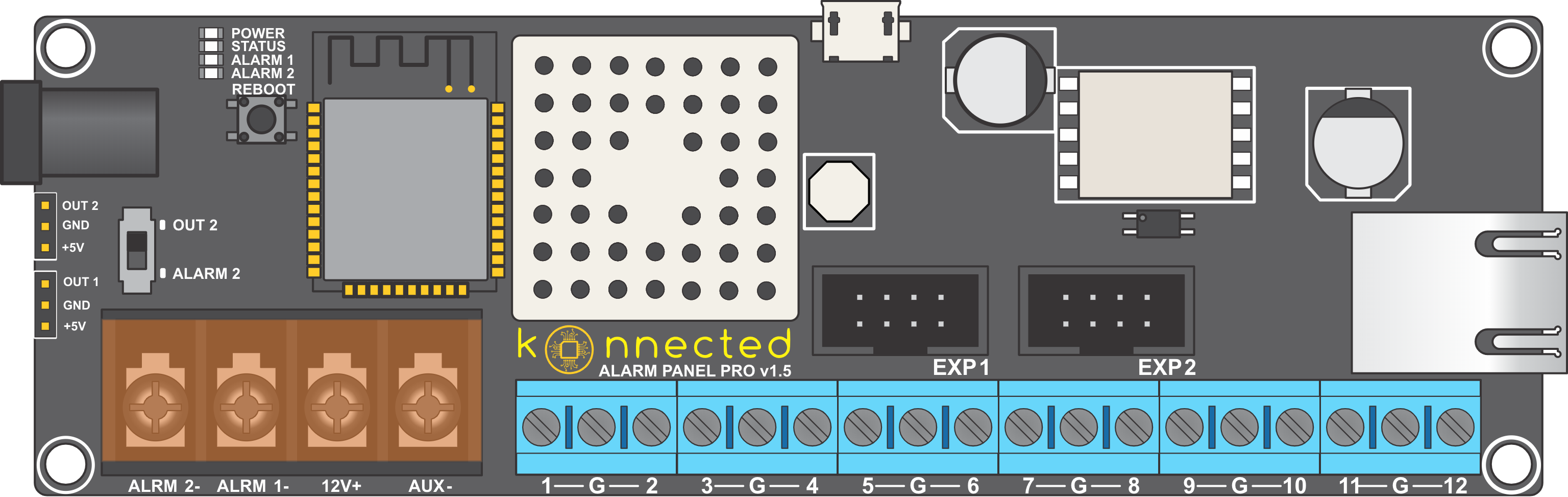
- Ethernet/PoE: The ethernet port on the right edge of the Alarm Panel Pro accepts a standard RJ45 ethernet connection. It can also be used to power the board through PoE with a PoE+ compatible (802.3at) switch or injector.
- Power Input: The DC barrel jack on the left edge of the device accepts a 5.5mm x 2.1mm DC power plug. Connect a 12VDC power supply here to power the device when used via WiFi or non-powered Ethernet. Also can be used to provide supplemental power for 12V devices when powered via PoE.
- Zones 1 - 8: The blue terminal blocks 1-8 correspond to zones 1-8 and can be used for either:
- Binary sensors (i.e. door, window, motion sensors, smoke)
- Digital sensors (i.e. temperature sensors)
- 3.3V output triggers
- Zones 9 - 12: Blue terminal blocks 9 - 12 correspond to Zones 9 - 12 and can be used for binary sensors only.
- (G)round Terminals: Ground terminals labeled G are spaced out for convenience in connecting alarm system sensors. Two ground pins labeled GND are found on the left edge of the device. All grounds are common.
- ALRM1-: Dedicated 12V switched circuit for sirens, strobes, etc. ALARM 1 is a switched ground/common -- connect the black wire from the siren/strobe to ALARM 1 and the red wire to 12V+.
- ALRM2-: Additional 12V switched circuit for sirens, strobes, etc. To activate this circuit, switch the toggle switch to ALARM 2. The ALRM2- terminal is also a switched ground/common, similar to ALRM1-
- AUX-: Un-switched 12V ground for AUX powered devices.
- 12V+: Un-switched 12V for AUX powered devices.
- Micro-USB: The micro-USB port on the top edge of the device is for manually accessing the firmware and/or advanced debugging.
- +5V: Two 5V supply pins on the left edge of the device provide up to 500mA of current for powering 5V relays, sensors, etc.
- OUT1: Dedicated 3.3V trigger output for triggering a relay or piezo.
- OUT2: Additional 3.3V trigger output. Enable this output by toggling the toggle switch to OUT2.
- EXP1: Connect an Alarm Panel Interface module to interface Zones 1-6 in-parallel to a traditional wired alarm system.
- EXP2: Connect an Alarm Panel Interface module to interface Zones 7-12 in-parallel to a traditional wired alarm system.